- 您现在的位置:买卖IC网 > Sheet目录471 > MAX19994AEVKIT# (Maxim Integrated)KIT EVAL FOR MAX19994A MIXER
�� �
�
�Dual,� SiGe,� High-Linearity,� 1200MHz� to� 2000MHz�
�Downconversion� Mixer� with� LO� Buffer/Switch�
�Reduced-Power� Mode�
�Each� channel� of� the� device� has� two� pins� (LO_ADJ__,�
�IF__SET)� that� allow� external� resistors� to� set� the� internal�
�bias� currents.� Nominal� values� for� these� resistors� are�
�given� in� Table� 1.� Larger� value� resistors� can� be� used� to�
�reduce� power� dissipation� at� the� expense� of� some� per-�
�formance� loss.� If� ±1%� resistors� are� not� readily� available,�
�substitute� with� ±5%� resistors.�
�Significant� reductions� in� power� consumption� can� also�
�be� realized� by� operating� the� mixer� with� an� optional� 3.3V�
�supply� voltage.� Doing� so� reduces� the� overall� power� con-�
�sumption� by� approximately� 47%.� See� the� 3.3V� Supply�
�AC� Electrical� Characteristics� table� and� the� relevant� 3.3V�
�curves� in� the� Typical� Operating� Characteristics� section.�
�IND_EXT_� Inductors�
�For� applications� requiring� optimum� RF-to-IF� and� LO-to-�
�IF� isolation,� connect� low-ESR� inductors� from� IND_EXT_�
�(pins� 15� and� 31)� to� ground.� When� improved� isolation�
�is� not� required,� connect� IND_EXT_� to� ground� using� 0� I�
�resistance.�
�Layout� Considerations�
�A� properly� designed� PCB� is� an� essential� part� of� any�
�RF/microwave� circuit.� Keep� RF� signal� lines� as� short� as�
�possible� to� reduce� losses,� radiation,� and� inductance.�
�The� load� impedance� presented� to� the� mixer� must� be�
�such� that� any� capacitance� from� both� IF_-� and� IF_+� to�
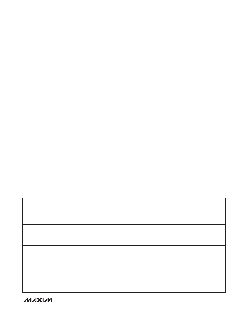
�Table� 1.� Component� Values�
�ground� does� not� exceed� several� picofarads.� For� the�
�best� performance,� route� the� ground� pin� traces� directly�
�to� the� exposed� pad� under� the� package.� The� PCB�
�exposed� pad� MUST� be� connected� to� the� ground� plane�
�of� the� PCB.� Use� multiple� vias� to� connect� this� pad� to� the�
�lower-level� ground� planes.� This� method� provides� a� good�
�RF/thermal-conduction� path� for� the� device.� Solder� the�
�exposed� pad� on� the� bottom� of� the� device� package� to�
�the� PCB.� The� MAX19994A� evaluation� kit� can� be� used� as�
�a� reference� for� board� layout.� Gerber� files� are� available�
�upon� request� at� www.maxim-ic.com� .�
�Power-Supply� Bypassing�
�Proper� voltage-supply� bypassing� is� essential� for� high-�
�frequency� circuit� stability.� Bypass� each� V� CC� pin� and�
�TAPMAIN/TAPDIV� with� the� capacitors� shown� in� the�
�Typical� Application� Circuit� (see� Table� 1� for� component�
�values).� Place� the� TAPMAIN/TAPDIV� bypass� capacitors�
�to� ground� within� 100� mils� of� the� pin.�
�Exposed� Pad� RF/Thermal� Considerations�
�The� exposed� pad� (EP)� of� the� MAX19994A’s� 36-pin� thin�
�QFN-EP� package� provides� a� low� thermal-resistance�
�path� to� the� die.� It� is� important� that� the� PCB� on� which� the�
�device� is� mounted� be� designed� to� conduct� heat� from�
�the� EP.� In� addition,� provide� the� EP� with� a� low-inductance�
�path� to� electrical� ground.� The� EP� MUST� be� soldered� to�
�a� ground� plane� on� the� PCB,� either� directly� or� through� an�
�array� of� plated� via� holes.�
�DESIGNATION�
�QTY�
�DESCRIPTION�
�COMPONENT� SUPPLIER�
�39pF� microwave� capacitors� (0402)�
�C1,� C8�
�2�
�1.8pF� for� Extended� RF� Band� applications�
�Murata� Electronics� North� America,� Inc.�
�(f� RF� =� 1.7GHz� to� 2GHz)�
�C2,� C7,� C14,� C16�
�C3,� C6�
�C4,� C5�
�C9,� C13,� C15,�
�C17,� C18�
�C10,� C11,� C12,�
�C19,� C20,� C21�
�L1,� L2,� L4,� L5�
�4�
�2�
�2�
�5�
�6�
�4�
�39pF� microwave� capacitors� (0402)�
�0.033� F� F� microwave� capacitors� (0603)�
�Not� used�
�0.01� F� F� microwave� capacitors� (0402)�
�150pF� microwave� capacitors� (0603)�
�120nH� wire-wound,� high-Q� inductors� (0805)�
�Murata� Electronics� North� America,� Inc.�
�Murata� Electronics� North� America,� Inc.�
�—�
�Murata� Electronics� North� America,� Inc.�
�Murata� Electronics� North� America,� Inc.�
�Coilcraft,� Inc.�
�10nH� wire-wound,� high-Q� inductors� (0603).� Smaller�
�L3,� L6�
�2�
�values� or� a� 0� I� resistor� can� be� used� at� the� expense� of�
�some� LO� leakage� at� the� IF� port� and� RF-to-IF� isolation�
�Coilcraft,� Inc.�
�performance� loss.�
�L7,� L8�
�2�
�4.7nH� inductor� (0603).� Installed� for� Extended� RF� Band�
�applications� only� (1.7GHz� to� 2GHz).�
�TOKO� America,� Inc.�
�25�
�发布紧急采购,3分钟左右您将得到回复。
相关PDF资料
MAX19995ETX+T
IC DOWNCONVERTER 2CH 36TQFN
MAX19995EVKIT#
EVALUATION KIT FOR MAX19995
MAX19996AEVKIT#
EVALUATION KIT FOR MAX19996A
MAX19996ETP+T
IC MIXER DOWNCONV 20-TQFN-EP
MAX19997AETX+T
IC DOWNCONVERTER 2CH 36TQFN
MAX19998ETP+
IC MIXER DOWNCONVERSION 20TQFN
MAX19999ETX+T
IC DOWNCONVERTER 2CH 36TQFN
MAX2009ETI+T
IC RF PREDISTORT ADJ 28-TQFN
相关代理商/技术参数
MAX19995AETX+
功能描述:上下转换器 High-Gain 1.2GHz to 2GHz Downconv RoHS:否 制造商:Texas Instruments 产品:Down Converters 射频:52 MHz to 78 MHz 中频:300 MHz LO频率: 功率增益: P1dB: 工作电源电压:1.8 V, 3.3 V 工作电源电流:120 mA 最大功率耗散:1 W 最大工作温度:+ 85 C 安装风格:SMD/SMT 封装 / 箱体:PQFP-128
MAX19995AETX+T
功能描述:上下转换器 High-Gain 1.7GHz to 2.2GHz Downconv RoHS:否 制造商:Texas Instruments 产品:Down Converters 射频:52 MHz to 78 MHz 中频:300 MHz LO频率: 功率增益: P1dB: 工作电源电压:1.8 V, 3.3 V 工作电源电流:120 mA 最大功率耗散:1 W 最大工作温度:+ 85 C 安装风格:SMD/SMT 封装 / 箱体:PQFP-128
MAX19995AEVKIT#
功能描述:射频开发工具 RoHS:否 制造商:Taiyo Yuden 产品:Wireless Modules 类型:Wireless Audio 工具用于评估:WYSAAVDX7 频率: 工作电源电压:3.4 V to 5.5 V
MAX19995ETX+
功能描述:上下转换器 High-Gain 1.7GHz to 2.2GHz Downconv RoHS:否 制造商:Texas Instruments 产品:Down Converters 射频:52 MHz to 78 MHz 中频:300 MHz LO频率: 功率增益: P1dB: 工作电源电压:1.8 V, 3.3 V 工作电源电流:120 mA 最大功率耗散:1 W 最大工作温度:+ 85 C 安装风格:SMD/SMT 封装 / 箱体:PQFP-128
MAX19995ETX+T
功能描述:上下转换器 High-Gain 1.7GHz to 2.2GHz Downconv RoHS:否 制造商:Texas Instruments 产品:Down Converters 射频:52 MHz to 78 MHz 中频:300 MHz LO频率: 功率增益: P1dB: 工作电源电压:1.8 V, 3.3 V 工作电源电流:120 mA 最大功率耗散:1 W 最大工作温度:+ 85 C 安装风格:SMD/SMT 封装 / 箱体:PQFP-128
MAX19995EVKIT#
功能描述:射频开发工具 RoHS:否 制造商:Taiyo Yuden 产品:Wireless Modules 类型:Wireless Audio 工具用于评估:WYSAAVDX7 频率: 工作电源电压:3.4 V to 5.5 V
MAX19996AETP+
功能描述:上下转换器 High-Gain 2GHz to 3.9GHz Downconv RoHS:否 制造商:Texas Instruments 产品:Down Converters 射频:52 MHz to 78 MHz 中频:300 MHz LO频率: 功率增益: P1dB: 工作电源电压:1.8 V, 3.3 V 工作电源电流:120 mA 最大功率耗散:1 W 最大工作温度:+ 85 C 安装风格:SMD/SMT 封装 / 箱体:PQFP-128
MAX19996AETP+T
功能描述:上下转换器 High-Gain 2GHz to 3.9GHz Downconv RoHS:否 制造商:Texas Instruments 产品:Down Converters 射频:52 MHz to 78 MHz 中频:300 MHz LO频率: 功率增益: P1dB: 工作电源电压:1.8 V, 3.3 V 工作电源电流:120 mA 最大功率耗散:1 W 最大工作温度:+ 85 C 安装风格:SMD/SMT 封装 / 箱体:PQFP-128